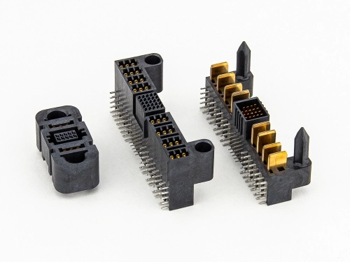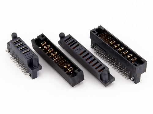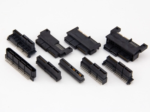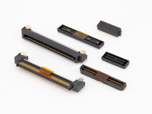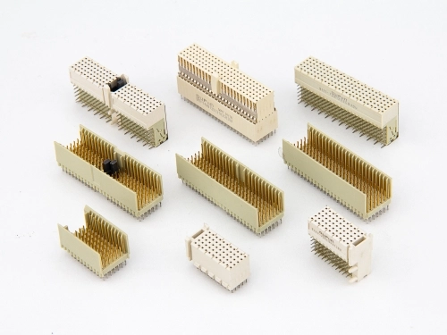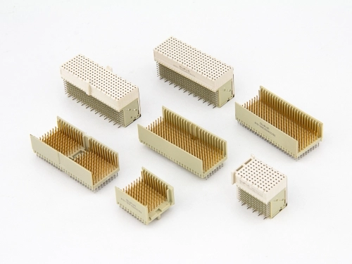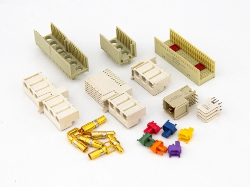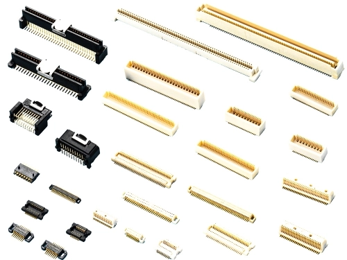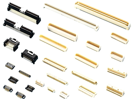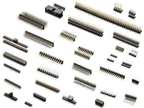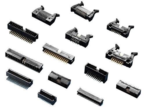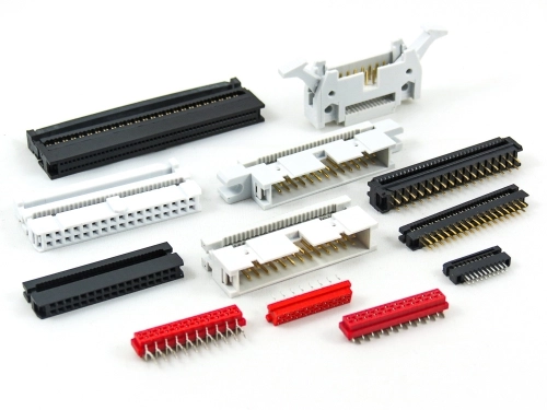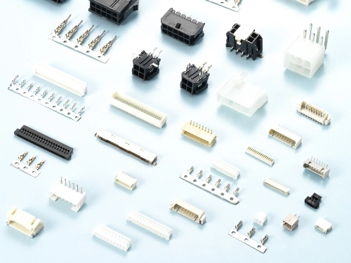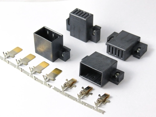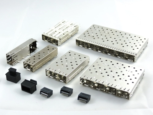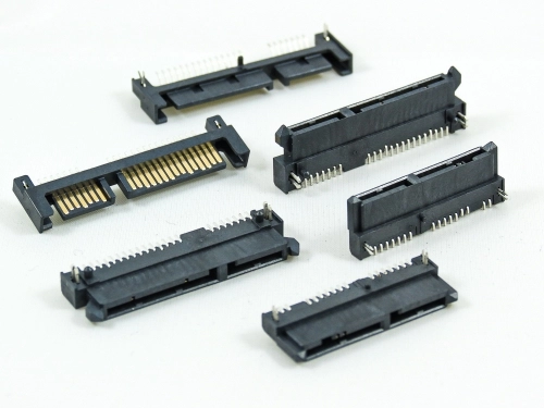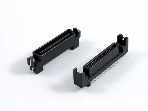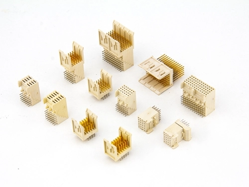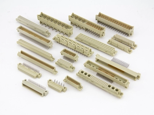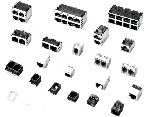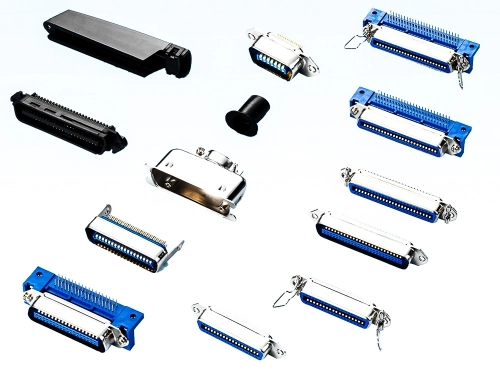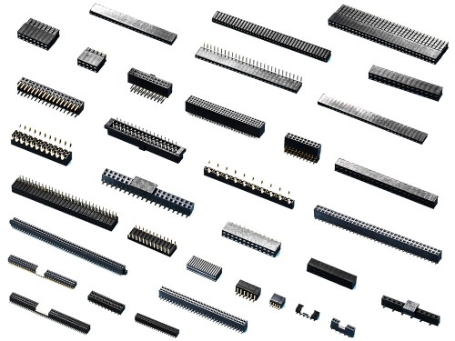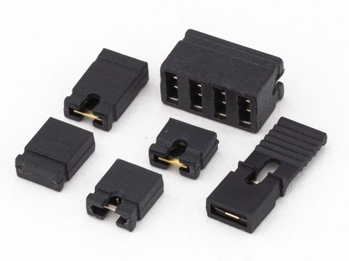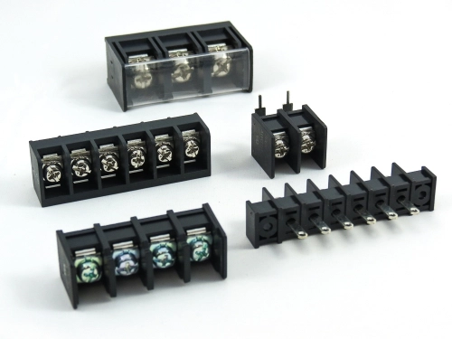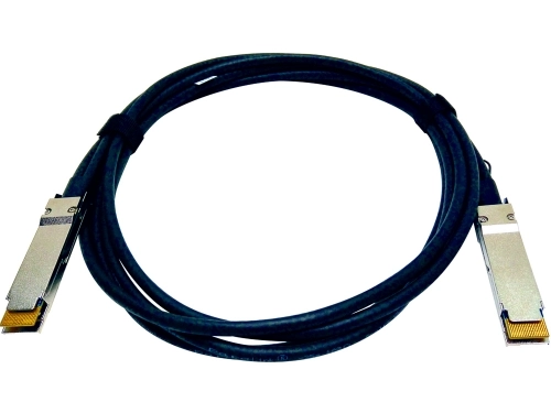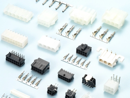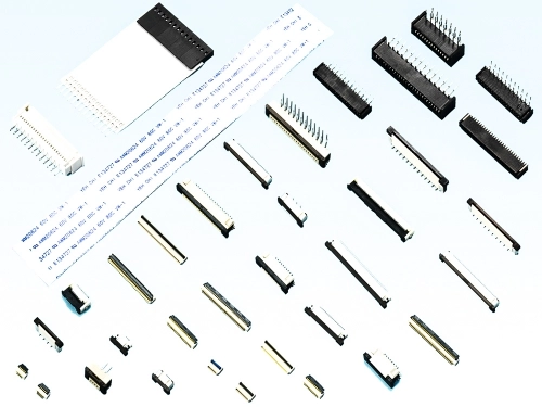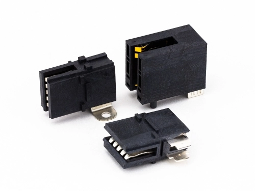
Board-to-board (BTB) connectors are electronic connectors connecting two printed circuit boards (PCBs). They enable electrical signals and power to flow seamlessly between each component, allowing the device, machine, or tool to turn on, and transmit directions or energy. Without these connectors, smartphones, laptops, data centers, automotive systems, and industrial equipment would malfunction frequently or flat-out not work.
You can find BTB connectors in various configurations, such as mezzanine, coplanar, or perpendicular. However, despite BTB connectors being mostly standardized, some systems will require grander performance. In said cases, high-speed board-to-board connectors should be used since they are specifically designed for applications where fast, consistent, and reliable transmission is not only mandatory but critical. However, how do you determine a high-speed BTB connector is worthy of being chosen for your product design?
No matter how strong and reliable a BTB connector is, some applications may need a component handling higher speeds, larger amounts of data, and stronger forms of protection. Attributes a “regular” board-to-board connector may not be able to provide. A high-speed board-to-board connector, on the other hand, is designed for these newer and more powerful applications. But, what should you be looking for when picking out the best high-speed BTB connectors? Well, there are a few key factors distinguishing “normal” BTB connectors and high-speed board-to-board connectors, such as:
In high-speed BTB connectors, maintaining impedance matching between the connector and the transmission line is crucial. Impedance matching is establishing efficient signal transfer and minimizing signal loss or distortion by making the resistance to alternating currents of one electrical system equal to the impedance of a connected part, which is typically 50, 85, or 100 ohms for high-speed signals. To guarantee maximum performance all components must be "on the same wavelength". Without this detail, you may run into three issues.
High signal integrity ensures data and power flow reliably and accurately between BTB connectors. Without high-quality engineering, the transmission of electrical signals between two printed circuit boards (PCBs) may face degradation, distortion, or interference. However, there will be some signal challenges regardless of the BTB connector quality. Data rates increasing means there is a higher chance of noise loss, and temperature fluctuations, vibrations, and humidity will also impede the performance of signal integrity. Carefully examine the design of its future space and implement safeguards to prevent these obstacles from slowing down your delivery.
Bandwidth refers to the range of frequencies, or data rates, the connector can efficiently transmit without significant signal degradation. It determines the maximum amount of data flowing through the connector in a given time, typically measured in Hertz (Hz) or gigabits per second (Gbps). If engineered correctly, a standard BTB connector will be able to provide moderate data rates up to a few Gbps while a high-speed BTB connector will delegate a minimum of 10Gbps or as much as 112 Gbps.
But, what exactly should you look for when choosing the right high-speed BTB connector? Oupiin Enterprise recommends identifying the data rates and frequencies your system will operate at, and then comparing them to the inspected electronic connector's shielding, controlled impedance, and minimized crosstalk. Although, picking an electronic connector with a bandwidth exceeding current needs will allow you to prepare for any future upgrades.
Shielding is the design of the used conductive materials protecting the connector's signal transmission paths from external electromagnetic interference (EMI) and preventing crosstalk between adjacent signal paths. Without proper shielding, signal integrity would be inadequate.
For instance, EMI will cause major disruptions when near external electromagnetic fields, increase the chance of crosstalk, hinder the ability to maintain signal integrity, and reduce the product's reliability. To prevent these complications, metal shields are integrated into the production of the BTB connector; grounding will be blended to designate a direct path for EMI to dissipate; usage of differential pair design will naturally cancel out excessive noise; and a multi-layered design will reduce interference. Altogether, remember three main facts explaining the need and services of a BTB connector's shielding.
Evaluate the amount of EMI in your product design to see what the device will be exposed to.
Prioritize electronic connectors with robust protection.
Opt for compact space utilization.
A BTB connector's contact design involves the physical configuration and materials used for the electrical contacts, which establish the connection between the two printed circuit boards (PCBs). Key features of a BTB connector's contact design are the types of contacts (blade-and-socket, spring-loaded contacts, pin-and-socket contacts, or floating contact designs), materials used, probability of low and stable contact resistance, the amount of pressure applied when the contact secures connection, level of durability during strenuous environments and performances, and the size of the pitch.
However, if the design happens to be too small, you may have to deal with an increased chance of structural complexity, requirement of more advanced materials, and potential degradation depending on how exposed the BTB connector is to moisture, dust, or corrosivity. But, when you do find a high-speed board-to-board connector with strong engineering, you will be given a performance with minimal signal loss, stable connections regardless of the situation, high-density mating in small spaces, and a longevity exceeding your expectations.
High-speed BTB connectors are usually constructed with high-quality materials promising low dielectric constants and low loss tangents, minimizing signal attenuation and distortion. Consider using high-performance plastics, ceramics, and metal alloys as they commonly achieve the desired electrical properties. However, we recommend also asking about the techniques used to promise mechanical reliability and stability, especially in environments with high vibration or temperature extremes.
The last step to include in your decision-making process is verifying performance under a litany of conditions. This can include simulations and/or testing, such as signal propagation, analyzing eye diagrams, and measuring pertinent parameters such as insertion loss, return loss, and jitter. Make sure the high-speed BTB connector survives these examinations to guarantee your business's product design isn't diminished when a user places them in said situations. This step may lengthen your deadline, but testing ensures these electronic connectors satisfy your required specifications.
By carefully confirming these decision-making details, you can ensure a reliable and efficient high-speed BTB connector is used while also minimizing the chance of unreasonable degradation. Fortunately for you, Oupiin Enterprise can provide documentation and examples highlighting the best of these attributes. We have been creating innovative, exceptional, and affordable high-speed board-to-board connectors since our inception decades ago. But, if you have any questions regarding what we offer or how to start the purchasing process, we recommend contacting one of our international locations. If you would like to talk with a representative from California, USA, send an email to sales@oupiin.com or call us at 1(661) 294-0228. For a representative from Taoyuan, Taiwan, call +886-3-3655030 or send an email to sales@oupiin.com.tw. We will happily respond within 24 hours with the answers you may be seeking.